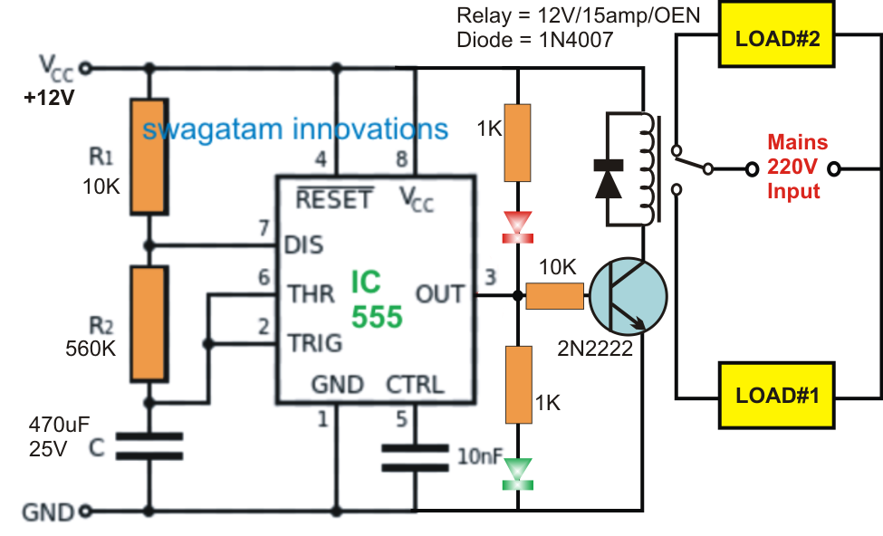
Ic 555 Timer Delay Relay Circuit
Time delay relay using 555 timer, proteus simulation and pcb design 555 timer circuits blinking Timer 555 circuit led relay ic circuits switching off homemade alternate two projects alternating astable 220v board mains diagram switch
How Does 555 Timer Work
Unplugging the drain: can a time delay circuit sequence be used to 555 timer tutorial: how it works and useful example circuits Ic 555 delay timer circuit
On off timer relay circuit diagram
Timer delay drain sequence unplugging floods prevent simpleTimer delay 555 relay proteus simulation Circuit delay 555 timer ic off time counterHow does 555 timer work.
Timer delay timers circuits eeweb elprocus astable modes monostableTwo sensors in arduino Alternate switching relay timer circuitTimer monostable multivibrator circuits transistor capacitor ws timing.

555 monostable multivibrator timer circuits circuit using schematic diagram stable input draw two electronic oscillator magnet unstable sensors talking transmitter
.
.


Time Delay Relay using 555 Timer, Proteus Simulation and PCB Design

two sensors in arduino

On Off Timer Relay Circuit Diagram

555 Timer Tutorial: How It Works and Useful Example Circuits

Unplugging the drain: Can a time delay circuit sequence be used to

Alternate Switching Relay Timer Circuit